3D Scanning Turbine Blade
Completed: December 2022
While working at the Mechanical Undergraduate Laboratory at my university, two of my tasks were to develop a workflow for reverse engineering objects using 3d scanning and also to create a series of trophies using a turbine blade, as seen below:
One of the turbine blades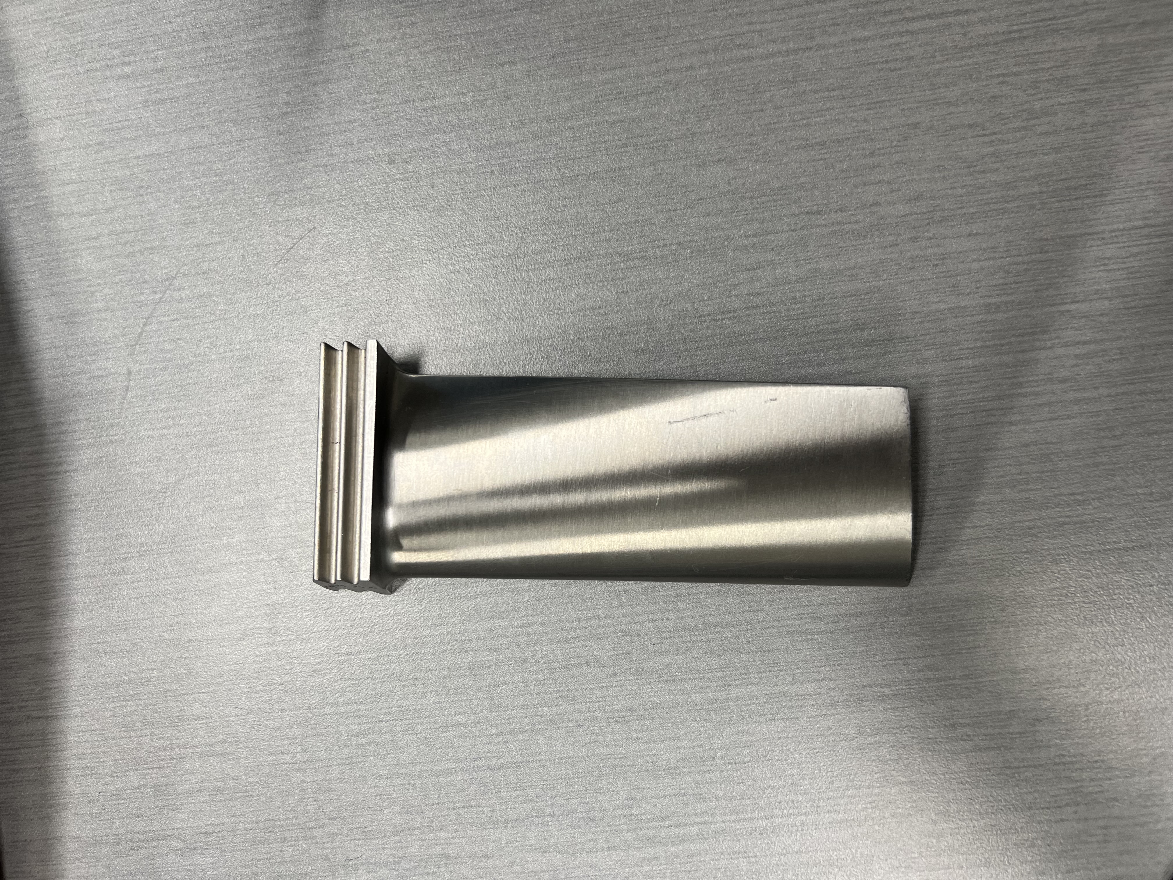
A test of the trophy was made by clamping a blade to a plate on the mill. This was inefficient for many reasons.
- The blades have an irregular shape, making it difficult to mount using clamps
- Every time a new blade would be processed, the references on the mill would have to be determined again.
My coworker suggested that since we have the 3D scanners and it’s something I’m already working on, why not scan a model of the blade and then 3D print a mould that can be used to secure the blade on the mill? As luck would have it, he also found a video by Making for Motorsports doing exactly that. It was released a couple of days before our conversation, so it was quite the coincidence. The video explained how to use Fusion 360 to make a model from a mesh.
So that’s what we did. We took a scan of the blade using a Roland LPX-600, imported it into Fusion and then made a model of the blade.
The scan of the blade on fusion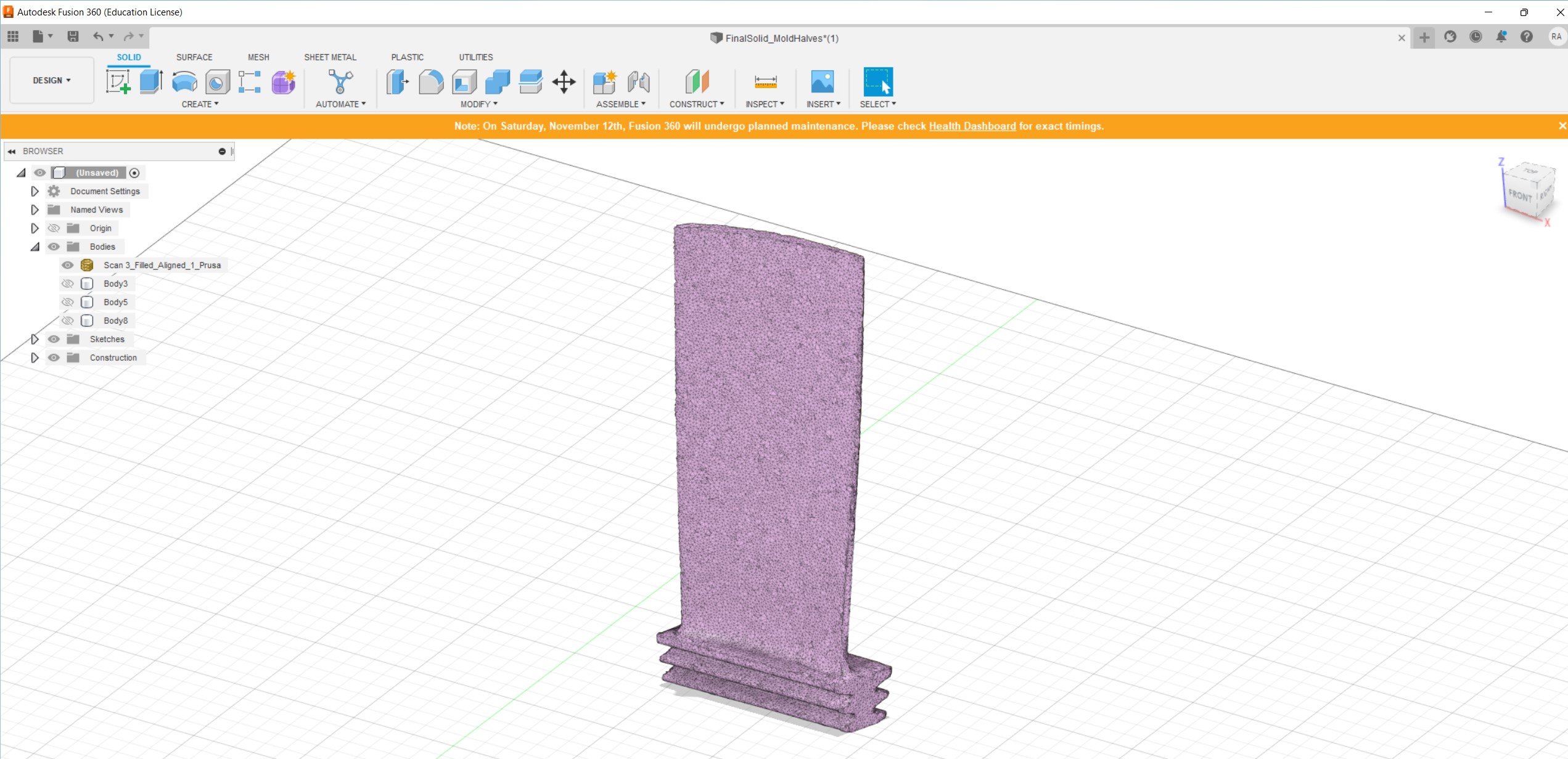
3d model of turbine blade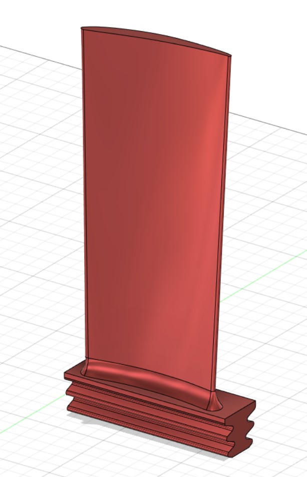
With the model made, we made a mould that would be used as a jig for the blades. See the images of the model below.
Half of the mould.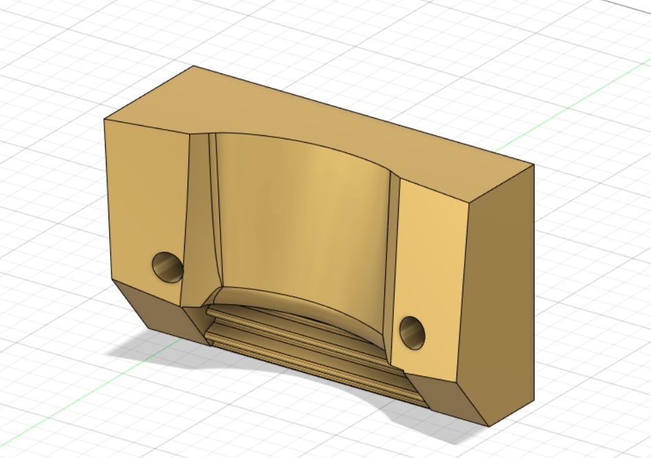
Other half of the mould.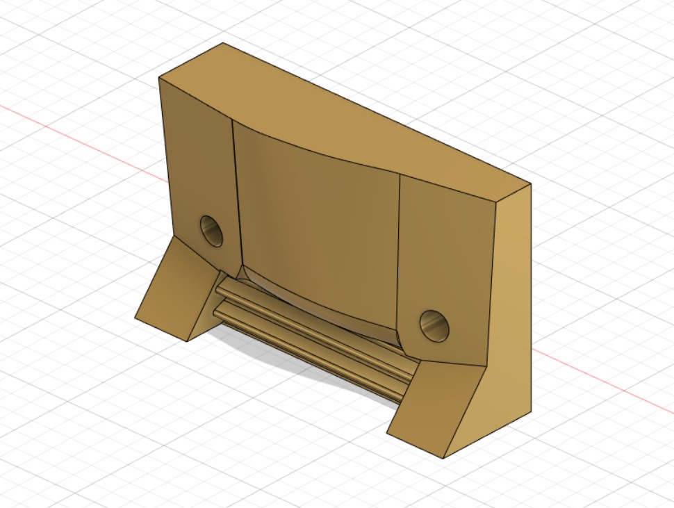
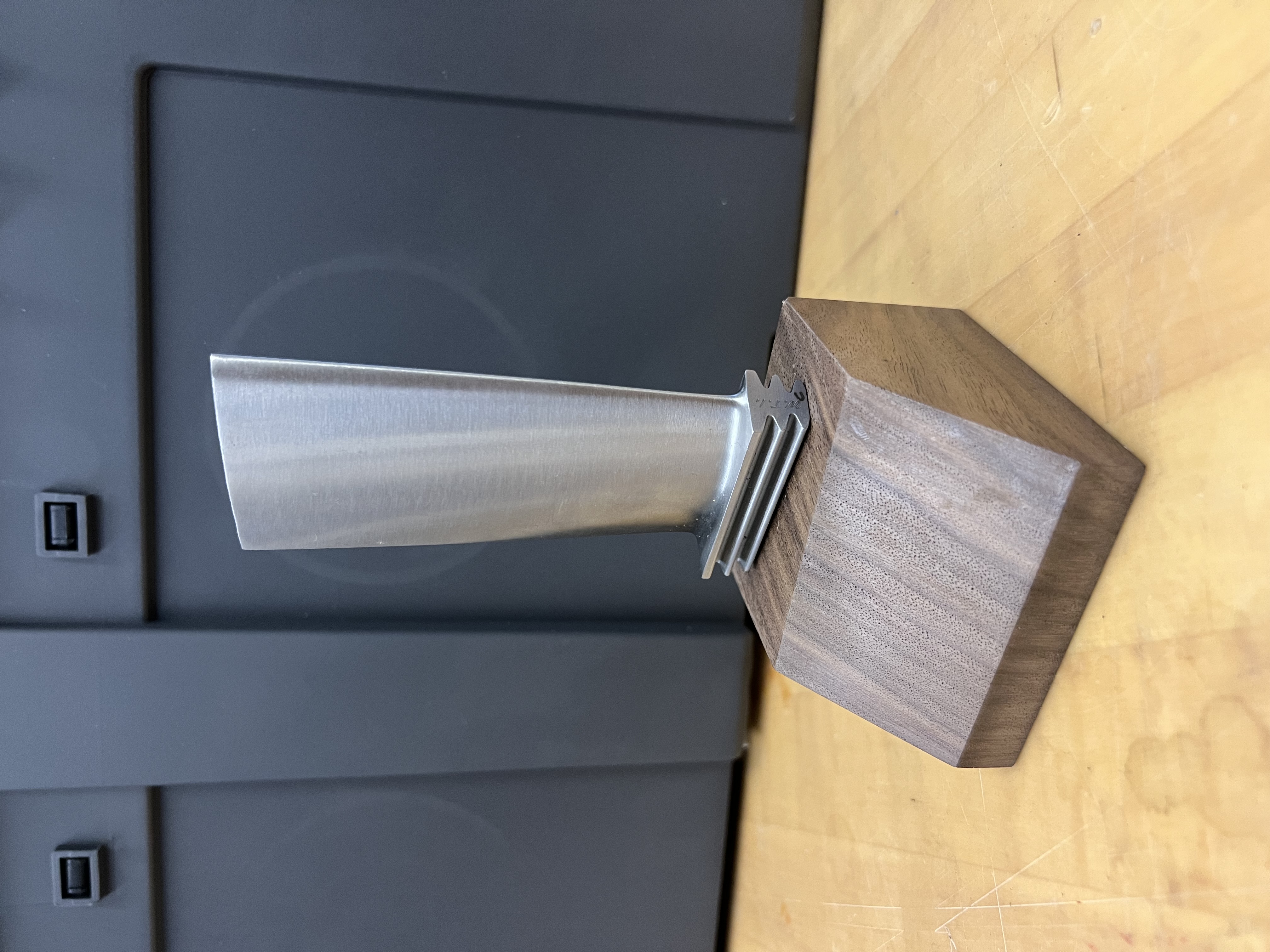
The assembled mould.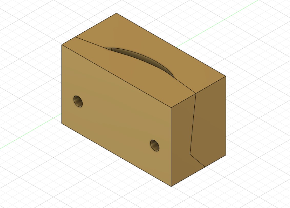
The mould with the blade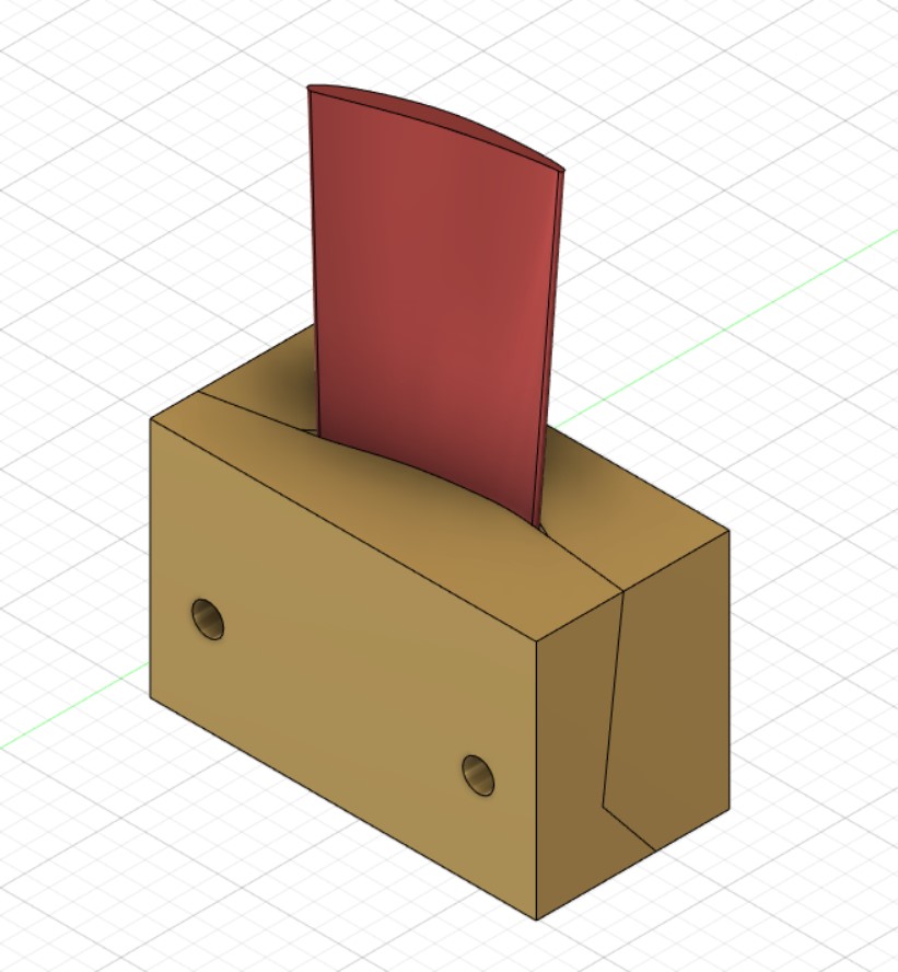
The completion of the mould marks the end of the 3D scanning/reverse engineering portion of the project. Next was to finish fabricating the trophies.
First, I used an aluminum plate as the base to secure the jig to. I used an end mill to square two sides of the plate. Then I drilled, countersunk and tapped holes that would be used to fasten the jig to the plate.
Milling plate edge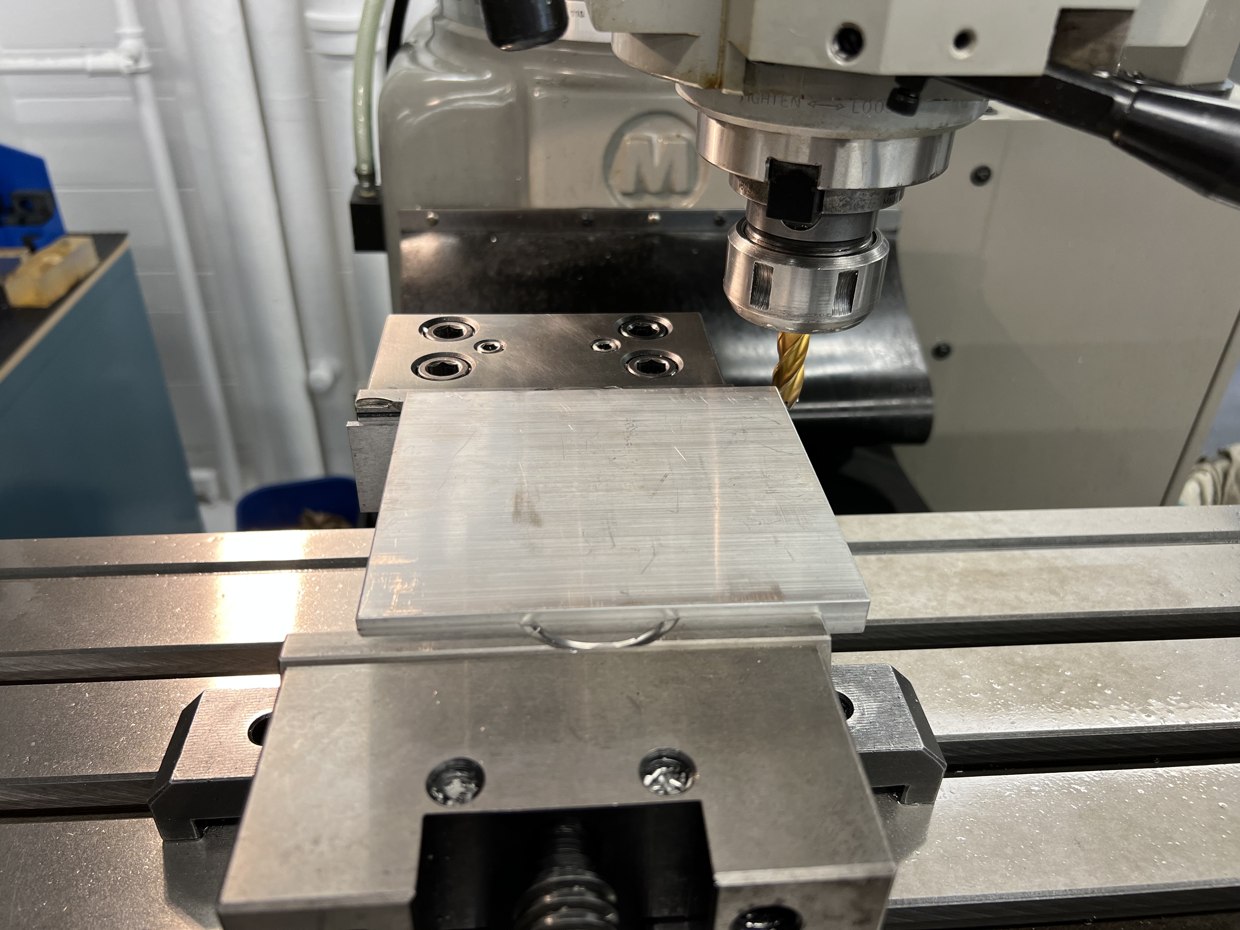
Plate mounted in mill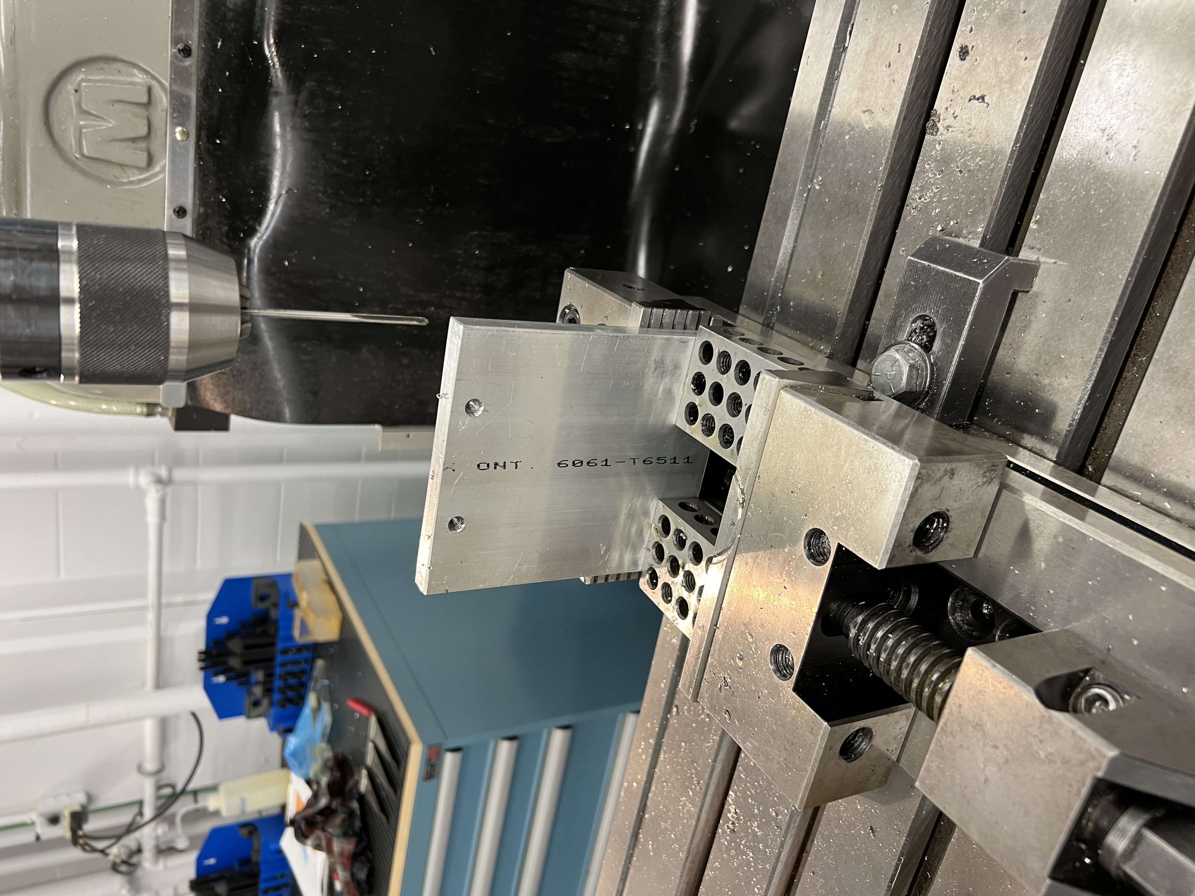
Once the plate was complete, it was secured to the mill, and the operations for the blades could begin. The jig with the blade assembled can be seen in the picture below. I used an edge finder to get the center of the blades and then drilled and reamed holes to fit the dowel pins. This was rinsed and repeated for 10 blades. The jig worked really well, but it’s not perfect. If I were going to improve it, I would design the mould so that half would stay permanently fixed to the plate, and then the other half would be removed to swap the blades. This would ensure that the jig didn’t move during swaps.
Blade secured to plate in the mill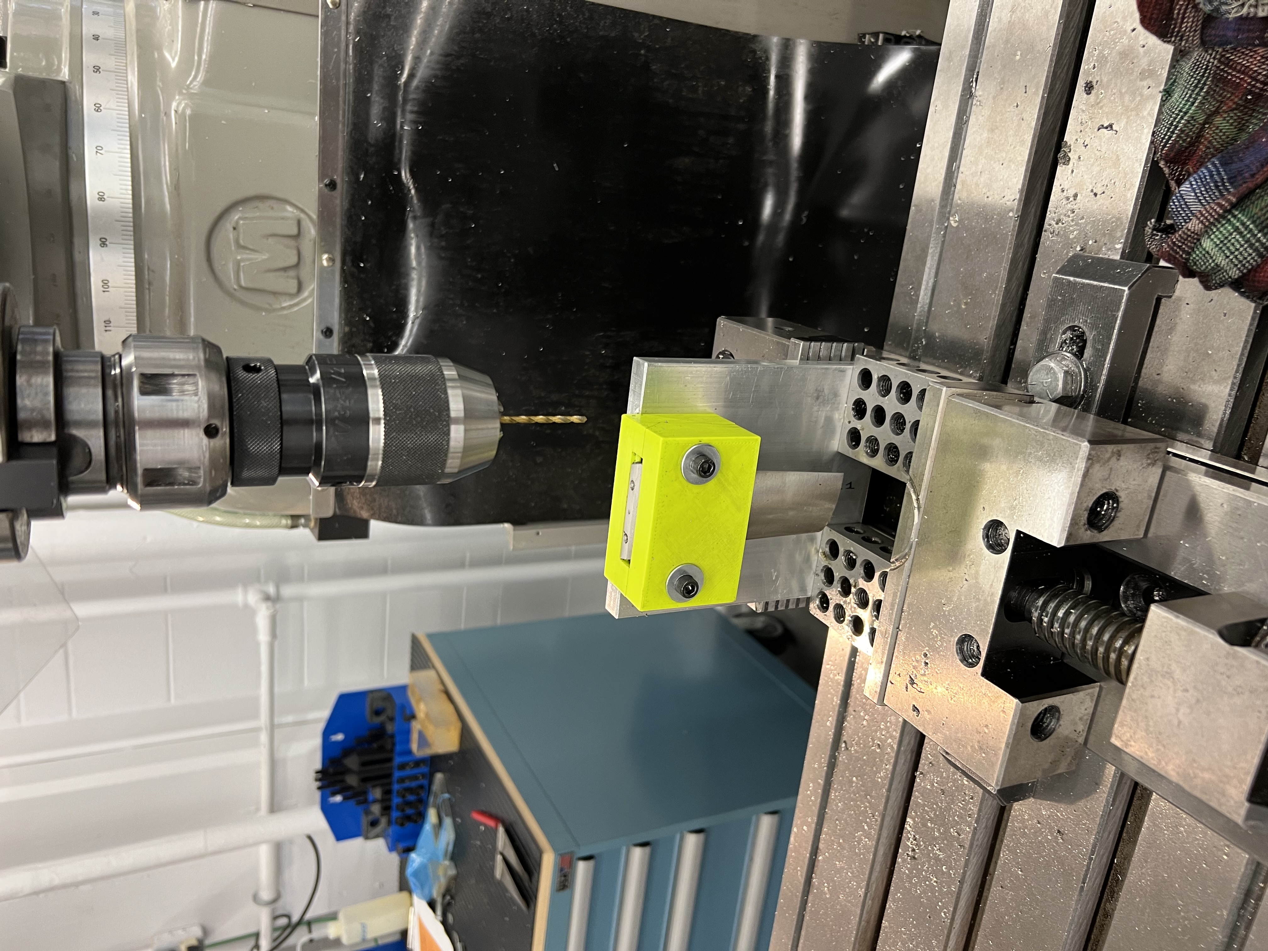
Once all the blades were completed, the wooden bases for the trophies had the equivalent holes drilled and reamed into them. The bases were finished with a Polyeurothane coating. Using the dowel pins, the blades were secured to the bases.
The finished result looks like this!
The finished trophy